Building Safe Implantable Devices
Our groundbreaking brain-computer interfaces (BCIs) have the potential to restore movement, enhance communication, and expand the human experience. We are achieving this through our implant, the Link, which directly interfaces with the brain to enable high-fidelity recording and modulation of neurons. The challenge then is, how do we ensure the safety of our technology? By prioritizing a meticulous approach to safety in our design and leveraging advanced assessment techniques, we have successfully launched clinical trials, providing our intracortical BCI implant to individuals living with paralysis and helping them regain their connection with the digital and physical worlds.
This blog post highlights our approach to safety assessment and some of our findings, which demonstrate a substantial improvement in safety and biocompatibility compared to prior technologies.
Why Implantable BCI?
Neuralink is building a high-bandwidth, generalized brain interface to restore autonomy to individuals with unmet medical needs today, and to unlock superhuman capabilities across many people in the future. These goals fundamentally require the ability to interact with large areas of the brain with exceptional precision. Methods for recording neural activity from outside of the brain, such as electroencephalography (EEG) and functional magnetic resonance imaging (fMRI), or from the surface of the brain, such as electrocorticography (ECoG), are not suitable for our objectives. These approaches either lack neuron-level resolution or are impractical for continuous daily use.
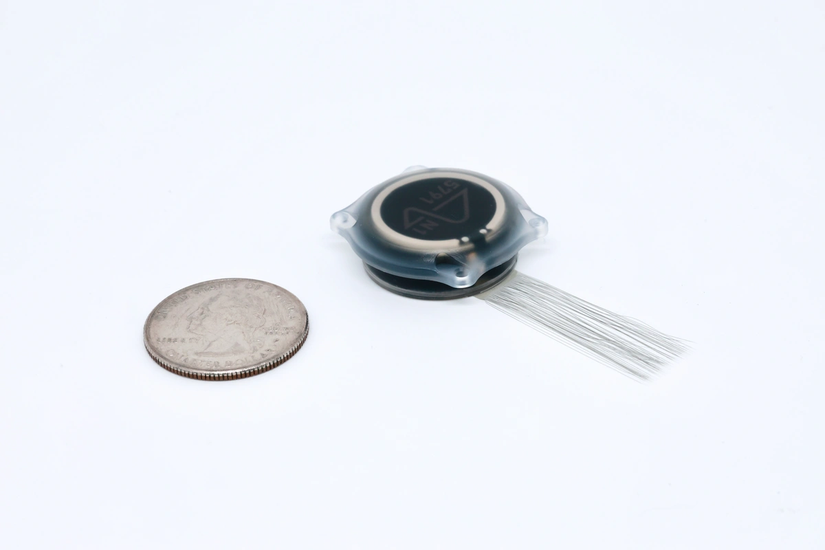
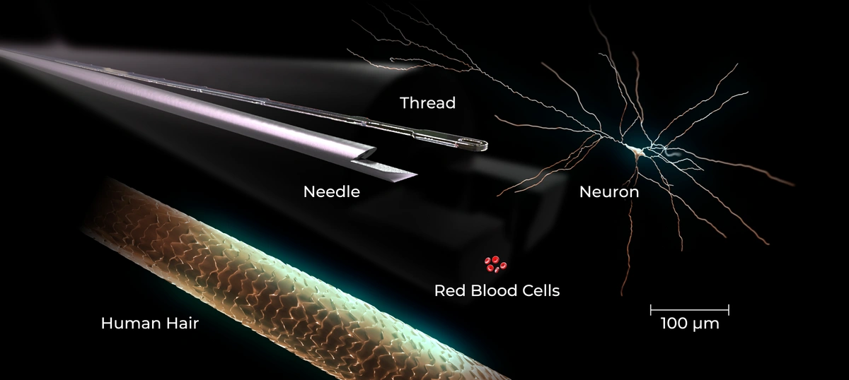
Our approach requires a procedure to place electrodes adjacent to neurons of interest. To do this, a small disk of skull, fit to the implant’s diameter, and dura (protective layer around the brain) are surgically removed. Next, microscopic threads extending from the implant (Fig 01), each one-tenth the thickness of a human hair (Fig 02), are inserted into the brain by a surgical robot. The robot is designed to further minimize tissue disruption by using precise insertion parameters and vessel avoidance, all overseen by board-certified neurosurgeons. Following thread insertions, the implant is mounted into the opening in the skull and then the skin is fully closed over it. While this approach requires neurosurgery, it is designed from the ground up to be minimally disruptive, leaving the patient with no visible change and minimal disturbance to cortical tissue.
Once implanted, the device must remain functioning and safe for a long time. One particular challenge is that the human body typically responds to foreign materials by encapsulating them in scar tissue. A significant reaction to our inserted threads could degrade the implant’s ability to detect and decode neural signals and potentially compromise the safety of our patients. We've designed safety and durability into the core architecture of the product, and through extensive preclinical studies, we've demonstrated highly favorable tissue response.
Evaluating Safety
At Neuralink, we approach preclinical safety from two perspectives: biocompatibility and procedural safety. Biocompatibility relates to how the body responds to the implanted material and relies on both in vitro and in vivo methods. Procedural safety encompasses the effects of the surgical process, including the surgical approach and implantation of the threads.
After developing confidence through extensive in vitro research, in vivo methods confirm these two aspects of safety. To do so, we rely on well-designed preclinical studies entailing both in-life and post-mortem analyses. During the in-life phase, animals are continuously monitored through daily veterinary physical and neurological examinations. Ultimately, safety must be demonstrated by inspection of the implanted tissue. Thus, after every study endpoint, a comprehensive analysis is performed to scrutinize the tissue response.
In addition to routine, post-mortem evaluations like organ weighing and macroscopic inspection, we use several advanced high-resolution imaging techniques to study the interface between host tissue and our device. One key tool, microcomputed tomography (micro-CT), helps us create detailed 3D images of the implant and surrounding tissue. This imaging method allows us to see features as small as 1 micrometer (the size of a typical bacterium), providing valuable insights into how the Link interfaces with the adjacent bone and how the implanted threads are situated within the brain tissue.
Alongside micro-CT, we collect and process thin slices of implanted tissue to inspect different biological features. Historically, the key limitation of BCIs has been inevitable encapsulation by scar tissue due a process known as glial encapsulation (Fig 03).
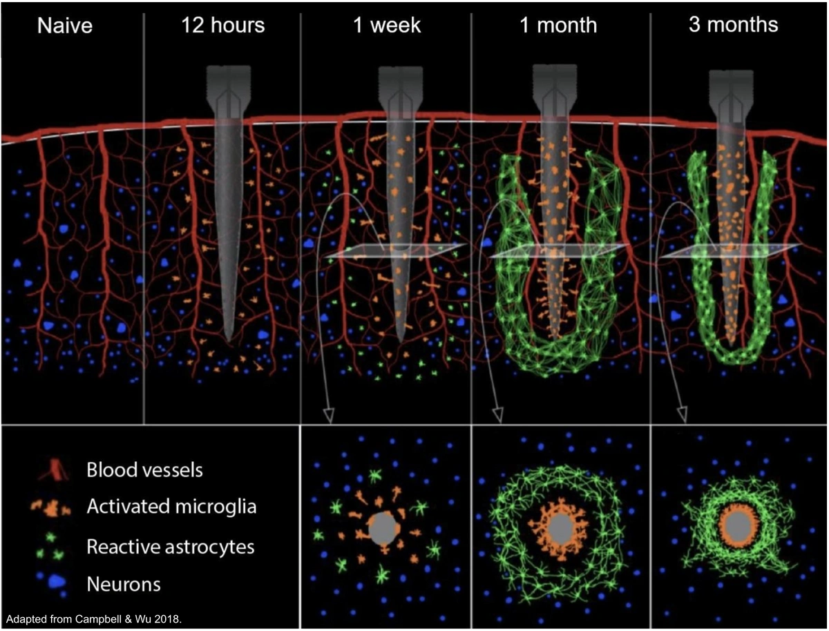
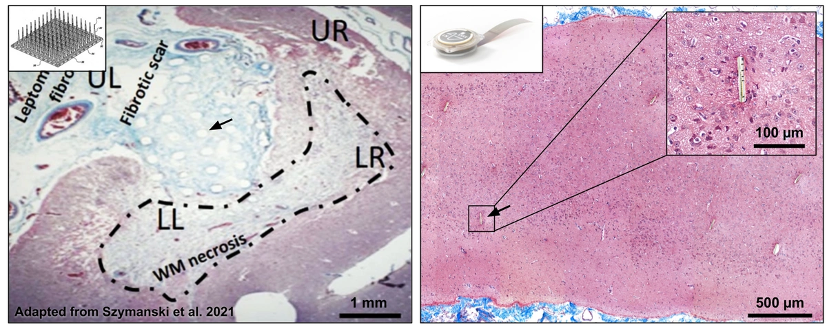
One way we assess the presence or absence of microglial response is by using a stain that dyes scar tissue blue—Masson’s Trichrome. Compared to published data on the response to other microelectrode arrays, we have consistently witnessed no encapsulation around our threads (Fig 04).
Another technique, immunohistochemistry, allows us to visualize key brain cells—neurons, microglia, and astrocytes—within the implanted tissue (Fig 05). This helps us understand the presence and health of these cells, offering a clearer picture of how our technology interacts with tissue on a cellular level.
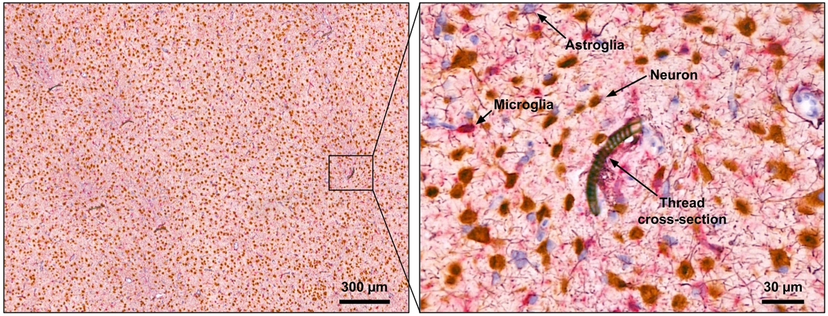
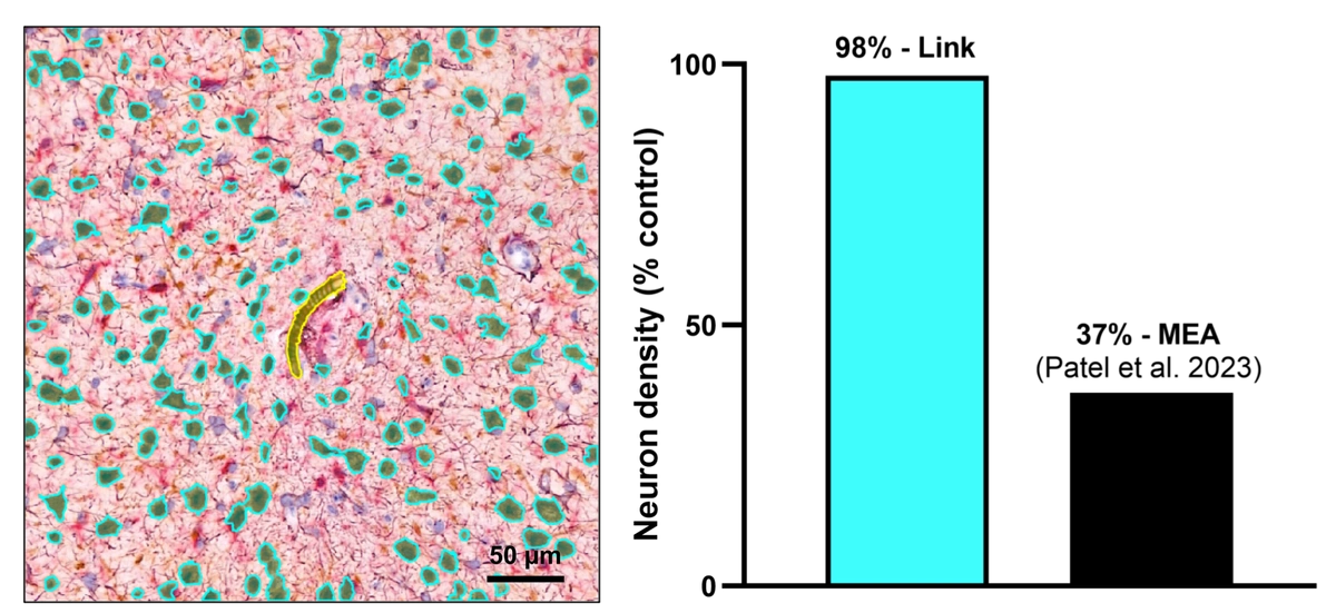
By applying cell detection image processing algorithms to photomicrographs of cortical tissue, we can count the number of neurons next to each thread and compare this number to unimplanted control tissue. Contrasting historic literature describing the response to other microelectrode arrays, our studies have shown minimal tissue response, maintaining about 98% of neurons at the thread interface.
As we continue to refine and enhance our systems, we invite forward-thinking experts to join our mission. If you’re excited to tackle the complex challenges in building safe, effective neural interfaces, explore our open roles and apply. Join our pioneering team to help shape the future of neurotechnology.
Acknowledgment
At Neuralink, we value our animal participants and honor their contributions by constantly improving their care and enrichment. Our engineering and preclinical teams systematically refine surgical techniques and device designs through a range of benchtop and preclinical studies. All studies involving animals are conducted under strict ethical oversight, adhering to and exceeding federal regulations while upholding the principles of the Three Rs.